

Injection molding tolerances refer to the acceptable range of variation in the dimensions of molded plastic parts.
These tolerances ensure that even with slight deviations in the manufacturing process, the parts will still fit together, function properly, and meet design requirements.

Think of it as a buffer zone for minor imperfections that might occur when injecting molten material into a mold.
Why do they matter?
Because when tolerances aren’t well-controlled, it can lead to parts that don’t fit together or work as intended, causing costly production issues and potential product failure.
For manufacturers aiming to produce high-quality, reliable parts, understanding and optimizing these tolerances is crucial.
By mastering injection molding tolerances, you can avoid unnecessary design revisions, reduce manufacturing costs, and ensure that your parts meet the highest quality standards.
Let’s explore how you can achieve that!
What Are Injection Molding Tolerances?

Injection molding tolerances refer to the permissible limits of dimensional variation in molded parts.
These tolerances allow for small deviations that naturally occur during the manufacturing process, ensuring that parts still function as intended despite slight differences in size or shape.
Without clear tolerances, parts might not fit together properly, leading to assembly errors or even product failure.
Why are tolerances so significant?
They are key to maintaining the quality and functionality of your parts.
Tolerances account for shrinkage, material flow, and other factors during the molding process that can cause parts to vary slightly from the original design.
By setting the correct tolerance range, manufacturers can produce parts consistently while minimizing the risk of defects.
Tolerance Ranges: Normal, Tight, and Very Tight
In injection molding, tolerances are categorized based on how precise they are:
Normal Tolerances: Typically range from +/- 0.1mm. This level of precision is suitable for most general-purpose parts where slight dimensional variations won’t impact functionality.
Tight Tolerances: Around +/- 0.05mm. These are used when parts must fit together more precisely or when minor deviations could affect performance.
Very Tight Tolerances: Usually around +/- 0.025mm or even tighter. These are used in high-precision industries such as medical devices and aerospace, where accuracy is critical.
Setting the right tolerance depends on the part’s application and material.
Some materials shrink more during cooling, requiring larger tolerances, while others allow for tighter control.
Here’s a breakdown of common tolerance ranges for various plastics:
Factors Influencing Injection Molding Tolerances
When working with injection molding, several factors impact the ability to hold precise tolerances.
Understanding these factors can help you optimize your design and manufacturing process, ensuring your parts meet the required specifications without unnecessary rework or waste.
Shrinkage

All plastic materials shrink as they cool down after being injected into the mold.
This shrinkage is one of the most critical factors influencing tolerances.
The amount a material shrinks can vary depending on its composition, cooling time, and mold design.
- Crystalline vs. Amorphous Materials: Crystalline materials like polypropylene (PP) and polyamide (PA) shrink more because their molecular structure rearranges during the cooling process. On the other hand, amorphous materials like ABS or PC have less pronounced shrinkage, making them easier to control in terms of tolerance.
Here’s a comparison of shrinkage rates for common materials:
| Material | Shrinkage Rate (%) |
|---|---|
| ABS | 0.4 – 0.8% |
| Polyamide (PA) | 0.7 – 1.4% |
| Polypropylene (PP) | 1.0 – 2.5% |
| Polycarbonate (PC) | 0.5 – 0.7% |
| High-Density Polyethylene (HDPE) | 1.5 – 3.0% |
How does shrinkage affect tolerances?
The higher the shrinkage, the more challenging it is to maintain tight tolerances.
Crystalline materials, with their higher shrinkage, often require more allowance in tolerance settings compared to amorphous materials.
Warpage

Warpage occurs when different parts of a molded piece cool unevenly, causing it to twist or bend.
This can be due to non-uniform wall thickness or improper cooling rates.
Warpage not only affects the visual appearance of the part but also its functional precision.
Strategies to minimize warpage:
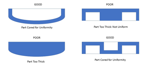
- Maintain uniform wall thickness: This ensures even cooling and minimizes the risk of deformation.
- Design with rounded corners and smooth transitions: Sharp changes in thickness can cause uneven cooling and lead to warping.
- Use ribs instead of increasing wall thickness: Ribs provide structural support without causing excessive shrinkage or cooling discrepancies.
Thermal Expansion
Plastic materials have higher thermal expansion coefficients compared to metals, which means their dimensions can change significantly with temperature fluctuations.
Parts molded at one temperature may expand or contract as they are exposed to different environments, affecting fit and function.
To reduce the impact of thermal expansion:
- Measure parts in controlled environments: Keep the temperature constant during inspections to ensure accurate dimensional measurements.
- Use materials with lower thermal expansion coefficients: Materials like PEEK and PC have better thermal stability, making them suitable for high-precision applications.
Part Design

The design of a part—including its geometry, wall thickness, and complexity—plays a crucial role in determining how well tolerances can be maintained.
Large, complex parts with varying wall thicknesses are more prone to shrinkage and warping, making it harder to achieve tight tolerances.
- Wall thickness: Keeping walls uniform throughout the part is essential for maintaining tolerance accuracy. Thicker walls take longer to cool, leading to higher shrinkage and potential deformation.
Here’s a table showing recommended wall thicknesses for common materials:
| Material | Recommended Wall Thickness (mm) |
|---|---|
| ABS | 1.1 – 3.5 mm |
| Polycarbonate (PC) | 1.0 – 3.8 mm |
| Polyamide (PA) | 0.7 – 2.9 mm |
| Polypropylene (PP) | 0.88 – 3.8 mm |
| HDPE | 0.7 – 5.0 mm |
Tooling Design

The design and quality of the mold are critical to achieving precise tolerances.
Factors like mold material, gate placement, and cooling system efficiency all affect how well the part adheres to the desired dimensions.
Mold design considerations for precision:
- Consistent heating and cooling: Uneven temperatures in the mold can cause parts to shrink inconsistently, making it hard to meet tight tolerances. Consistent cooling systems help minimize these issues.
- Gate placement: Improper gate location can cause uneven material flow, leading to shrinkage and warping. Multiple gates might be necessary for large or complex parts to ensure even distribution of molten plastic.
By taking these factors into account and carefully optimizing each element, manufacturers can better control the dimensional accuracy of their injection-molded parts.
This approach helps ensure the final product performs as intended, with minimal deviation from the design.
Best Practices for Optimizing Injection Molding Tolerances

Optimizing injection molding tolerances is key to producing high-quality parts with minimal deviations.
By adopting best practices in design, material selection, tooling, and process control, manufacturers can consistently achieve the desired tolerances for their products.
Let’s explore these practices in detail.
Design for Manufacturability (DFM)
Design for Manufacturability (DFM) is essential when creating parts that need to adhere to tight tolerances.
DFM principles focus on designing parts that are easy and cost-effective to manufacture while minimizing errors like warpages and dimensional inconsistencies.
Wall Thickness: Consistent wall thickness is crucial for uniform cooling, which directly impacts shrinkage and dimensional accuracy. When wall thickness varies, parts may cool unevenly, leading to warpage or incorrect dimensions.
Draft Angles: Adding draft angles to vertical surfaces helps parts release smoothly from the mold, reducing the risk of warping or dimensional inaccuracies. A draft angle of 1.5° to 2° is usually recommended for most parts.
Support Features: Instead of thickening walls to add strength, using features like ribs can enhance structural integrity while minimizing material use. Ribs reduce shrinkage and cooling time, leading to more consistent tolerances.
Example: A part with uniformly thick walls and carefully placed ribs will cool evenly, reducing the risk of shrinkage-related defects.
Material Selection

Choosing the right material for your application is one of the most significant factors affecting injection molding tolerances.
Different materials have different shrinkage rates and thermal expansion properties, which influence the precision of the final part.
- Shrinkage Rates: Materials like ABS or PC have lower shrinkage rates, making them ideal for parts with tight tolerances. On the other hand, materials like PP or PE may have higher shrinkage, which can lead to greater dimensional variance.
Selecting a material that matches the specific application needs and tolerance requirements is crucial.
For example, if your part demands high precision, using a material like PC or ABS would be more beneficial than a high-shrinkage material like PP.
Tooling Optimization

The design and optimization of the mold tooling directly impact the ability to maintain tight tolerances during production.
Tooling factors like gate location, ejector pin placement, and cooling system design all contribute to dimensional accuracy.
Gate Location: Proper gate placement ensures even filling of the mold, minimizing shrinkage and warpage. Multiple gates may be necessary for complex or large parts to prevent uneven material flow, which can lead to dimensional inaccuracies.
Ejector Pin Design: The location and design of ejector pins are critical to preventing distortion as parts are removed from the mold. Pins should be positioned to ensure smooth part ejection without damaging the surface or altering dimensions.
Real-Time Monitoring: Embedding sensors in the mold allows for real-time monitoring of pressure, temperature, and fill time. These sensors help adjust the process on the go, ensuring consistent results throughout the production run.
Example: A mold with well-placed gates and consistent cooling will produce parts with minimal warpage and greater dimensional accuracy.
Process Controls
Effective process control is essential for maintaining consistent tolerances in injection molding.
The process parameters, such as pressure, temperature, and cooling time, must be carefully controlled and monitored to minimize variability.
Pressure and Temperature Sensors: Embedding sensors in the mold help track the molding process in real time, providing valuable data on pressure and temperature. This feedback allows for quick adjustments, ensuring that each part meets the required tolerances.
Standardizing Environmental Conditions: External factors like ambient temperature and humidity can affect material properties and process performance. Standardizing the environmental conditions in the production area ensures that parts are molded consistently, minimizing variations.
Example: Controlling the cooling time, temperature, and pressure during each shot can help reduce the chances of part defects and improve dimensional consistency.
Injection Molding Tolerance Standards

Understanding and adhering to standardized tolerance guidelines is essential for ensuring consistent and reliable quality in injection-molded parts.
Standards like GB/T 14486-2008 and DIN 16901 offer well-defined parameters for allowable deviations in part dimensions, helping manufacturers achieve high precision.
Overview of Standards
GB/T 14486-2008: This Chinese national standard outlines tolerances for plastic parts, providing a framework for manufacturers to follow when producing precision components. It categorizes tolerances into various levels, helping manufacturers choose the appropriate tolerance range based on the part’s application and required precision.
DIN 16901: A German standard for plastics, DIN 16901 also offers guidelines for tolerances and focuses on maintaining functionality and fit in molded parts. This standard is widely used in Europe and is recognized for its stringent requirements, especially for complex and precise components.
These standards play a key role in determining the acceptable deviation range for dimensions, ensuring parts fit together properly and perform as intended.
Tolerance Levels: Commercial, Medium, and Fine
Tolerance levels are generally categorized into three classes—commercial, medium, and fine.
Each level reflects the acceptable degree of variation based on the application, precision needed, and manufacturing costs.
Fine tolerances are more expensive to achieve, while commercial tolerances are more cost-effective but less precise.
In general, commercial tolerances are suitable for parts that do not require tight fits, such as cosmetic components.
Medium tolerances are ideal for functional parts that need a balance between precision and cost-effectiveness, while fine tolerances are used in high-precision applications, such as medical devices or aerospace components.
Choosing the Right Tolerance Standard

The choice between tolerance levels depends on the specific needs of the project.
For parts that require tight assembly or are part of a complex mechanism, fine tolerances should be prioritized.
On the other hand, commercial tolerances may be sufficient for non-critical parts, where aesthetic or cost factors take precedence over extreme precision.
Common Challenges in Maintaining Tolerances
In injection molding, maintaining precise tolerances can be challenging due to various factors that influence part dimensions and consistency.
Two of the most common challenges are complexity in multi-cavity tools and large part dimensions.
Complexity in Multi-Cavity Tools
Multi-cavity molds are designed to produce multiple parts in a single cycle, increasing production efficiency.
However, maintaining consistent tolerances across all cavities can be difficult due to variations in cooling rates and pressure distribution.
Cooling Consistency: In multi-cavity molds, each cavity may not cool at the same rate, leading to slight dimensional differences between parts. If one cavity cools faster than the others, the part may shrink more, affecting the overall fit and function.
Pressure Distribution: Injection pressure may vary slightly between cavities, causing minor differences in part dimensions. This can be particularly problematic when tight tolerances are required for parts that must fit together during assembly.
To mitigate these issues, high-precision mold design is critical, ensuring even cooling and pressure distribution across all cavities.
Additionally, regular maintenance and monitoring of the mold can help maintain consistency over time.
Large Part Dimensions

Large parts present their own set of challenges when it comes to maintaining tolerances.
Material shrinkage tends to be more pronounced in larger parts, leading to greater dimensional variation.
Shrinkage Variability: Larger parts typically experience more material shrinkage during cooling, which can result in dimensional changes across different areas of the part. This can cause warping or distortion, making it difficult to achieve tight tolerances.
Longer Cooling Times: Large parts take longer to cool, increasing the likelihood of uneven cooling, which exacerbates shrinkage and tolerance issues.
To minimize these challenges, manufacturers can use uniform wall thicknesses and ensure proper cooling channel design in the mold to achieve more consistent shrinkage and dimensional stability.
Measurement and Inspection Techniques

Ensuring that injection-molded parts meet the required tolerances is crucial for their functionality and quality.
Various measurement and inspection techniques are used to verify dimensions and identify defects. Let’s explore the most common methods:
Visual Inspection
A basic but effective first step in the inspection process, visual inspection allows manufacturers to quickly identify surface defects such as warping, sink marks, and part misalignment.
While it’s not a precise measurement method, it helps catch obvious flaws before moving on to more detailed inspections.
Manual Measurement
For simple parts with fewer critical dimensions, manual measurement tools such as calipers and micrometers are used.
These tools provide quick and accurate measurements for verifying dimensions within tolerance ranges, typically for parts with looser tolerances or low complexity.
While manual measurements are effective, they are best suited for straightforward components and require skill and experience to use consistently.
Automated Measurement
For more complex parts or those requiring tight tolerances, automated measurement systems like Coordinate Measuring Machines (CMMs) and Vision Systems offer precise and comprehensive dimensional analysis.
These systems can measure multiple critical dimensions at once, ensuring parts meet specifications with minimal variation.
- CMMs use a probe to physically touch various points on the part, providing highly accurate data on dimensional tolerances.
- Vision Systems use cameras to capture images of the part and compare them to digital specifications, which is especially useful for non-contact inspection of fragile or delicate parts.
First Article Inspection (FAI)
First Article Inspection (FAI) is a comprehensive verification process performed on the first part produced in a production run.
It involves inspecting all critical dimensions, material properties, and part features to ensure they meet the design’s tolerance requirements.
This step is essential in validating that the production process is set up correctly and will produce parts that consistently meet specifications throughout the run.
FAQ About Injection Molding Tolerances
In general, commercial tolerances are suitable for parts that do not require tight fits, such as cosmetic components.
Medium tolerances are ideal for functional parts that need a balance between precision and cost-effectiveness, while fine tolerances are used in high-precision applications, such as medical devices or aerospace components.
Choosing the Right Tolerance Standard
The choice between tolerance levels depends on the specific needs of the project.
For parts that require tight assembly or are part of a complex mechanism, fine tolerances should be prioritized.
On the other hand, commercial tolerances may be sufficient for non-critical parts, where aesthetic or cost factors take precedence over extreme precision.
Common Challenges in Maintaining Tolerances
In injection molding, maintaining precise tolerances can be challenging due to various factors that influence part dimensions and consistency.
Two of the most common challenges are complexity in multi-cavity tools and large part dimensions.
Complexity in Multi-Cavity Tools
Multi-cavity molds are designed to produce multiple parts in a single cycle, increasing production efficiency.
However, maintaining consistent tolerances across all cavities can be difficult due to variations in cooling rates and pressure distribution.
Cooling Consistency: In multi-cavity molds, each cavity may not cool at the same rate, leading to slight dimensional differences between parts. If one cavity cools faster than the others, the part may shrink more, affecting the overall fit and function.
Pressure Distribution: Injection pressure may vary slightly between cavities, causing minor differences in part dimensions. This can be particularly problematic when tight tolerances are required for parts that must fit together during assembly.
To mitigate these issues, high-precision mold design is critical, ensuring even cooling and pressure distribution across all cavities.
Additionally, regular maintenance and monitoring of the mold can help maintain consistency over time.
Large Part Dimensions
Large parts present their own set of challenges when it comes to maintaining tolerances.
Material shrinkage tends to be more pronounced in larger parts, leading to greater dimensional variation.
Shrinkage Variability: Larger parts typically experience more material shrinkage during cooling, which can result in dimensional changes across different areas of the part. This can cause warping or distortion, making it difficult to achieve tight tolerances.
Longer Cooling Times: Large parts take longer to cool, increasing the likelihood of uneven cooling, which exacerbates shrinkage and tolerance issues.
To minimize these challenges, manufacturers can use uniform wall thicknesses and ensure proper cooling channel design in the mold to achieve more consistent shrinkage and dimensional stability.
Measurement and Inspection Techniques
Ensuring that injection-molded parts meet the required tolerances is crucial for their functionality and quality.
Various measurement and inspection techniques are used to verify dimensions and identify defects. Let’s explore the most common methods:
Visual Inspection
A basic but effective first step in the inspection process, visual inspection allows manufacturers to quickly identify surface defects such as warping, sink marks, and part misalignment.
While it’s not a precise measurement method, it helps catch obvious flaws before moving on to more detailed inspections.
Manual Measurement
For simple parts with fewer critical dimensions, manual measurement tools such as calipers and micrometers are used.
These tools provide quick and accurate measurements for verifying dimensions within tolerance ranges, typically for parts with looser tolerances or low complexity.
While manual measurements are effective, they are best suited for straightforward components and require skill and experience to use consistently.
Automated Measurement
For more complex parts or those requiring tight tolerances, automated measurement systems like Coordinate Measuring Machines (CMMs) and Vision Systems offer precise and comprehensive dimensional analysis.
These systems can measure multiple critical dimensions at once, ensuring parts meet specifications with minimal variation.
- CMMs use a probe to physically touch various points on the part, providing highly accurate data on dimensional tolerances.
- Vision Systems use cameras to capture images of the part and compare them to digital specifications, which is especially useful for non-contact inspection of fragile or delicate parts.
First Article Inspection (FAI)
First Article Inspection (FAI) is a comprehensive verification process performed on the first part produced in a production run.
It involves inspecting all critical dimensions, material properties, and part features to ensure they meet the design’s tolerance requirements.
This step is essential in validating that the production process is set up correctly and will produce parts that consistently meet specifications throughout the run.
FAQ About Injection Molding Tolerances
Conclusion

Understanding and optimizing injection molding tolerances is crucial for achieving high-quality, functional parts.
Factors like material selection, design considerations, and process control all play a role in maintaining precise tolerances and minimizing defects.
Ready to take your injection molding projects to the next level?
Contact us today to ensure your parts meet the highest standards for precision and performance.
Related Articles
Structural Foam Injection Molding: Benefits and Applications
Liquid Silicone Rubber Injection Molding: A Detailed Guide
Comprehensive Guide to Rubber Injection Molding
Ultimate Guide to EVA Injection Molding
Thermoplastic Elastomer (TPE) Injection Molding Guide
Ultimate Guide to Overmolding: Techniques
10 Common Plastic Resins for Injection Molding
Thermoforming vs Injection Molding: Key Differences
Understanding 2K Injection Molding: Process
PEEK Injection Molding: Properties, Benefits, and Tips
Injection Molding Defects and Their Solutions
Reaction Injection Molding: Process, Benefits and Uses
The Ultimate Guide to Injection Molding
Medical Injection Molding: Precision in Healthcare
Comprehensive Guide to Metal Injection Molding (MIM)
Parting Line Injection Molding Guide
Sink Marks Prevention in Injection Molding
What is Injection Molding Back Pressure?


 English
 Arabic
 German
 Spanish
 French
 Italian
 Javanese
 Korean
 Portuguese
 Russian
 Hindi
 Chinese
